Z Scale Model Train Layout on Apartment Windowsill #
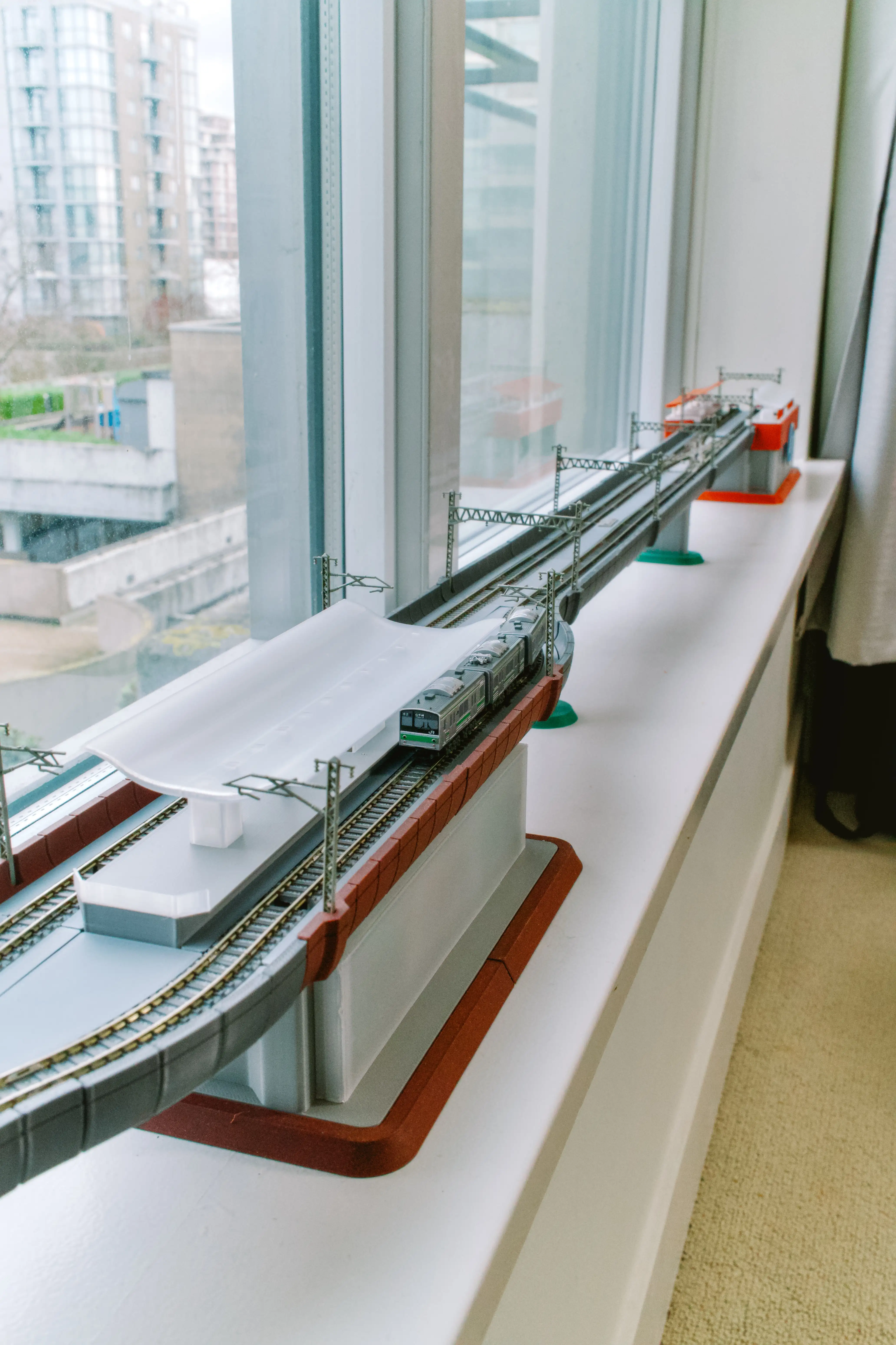
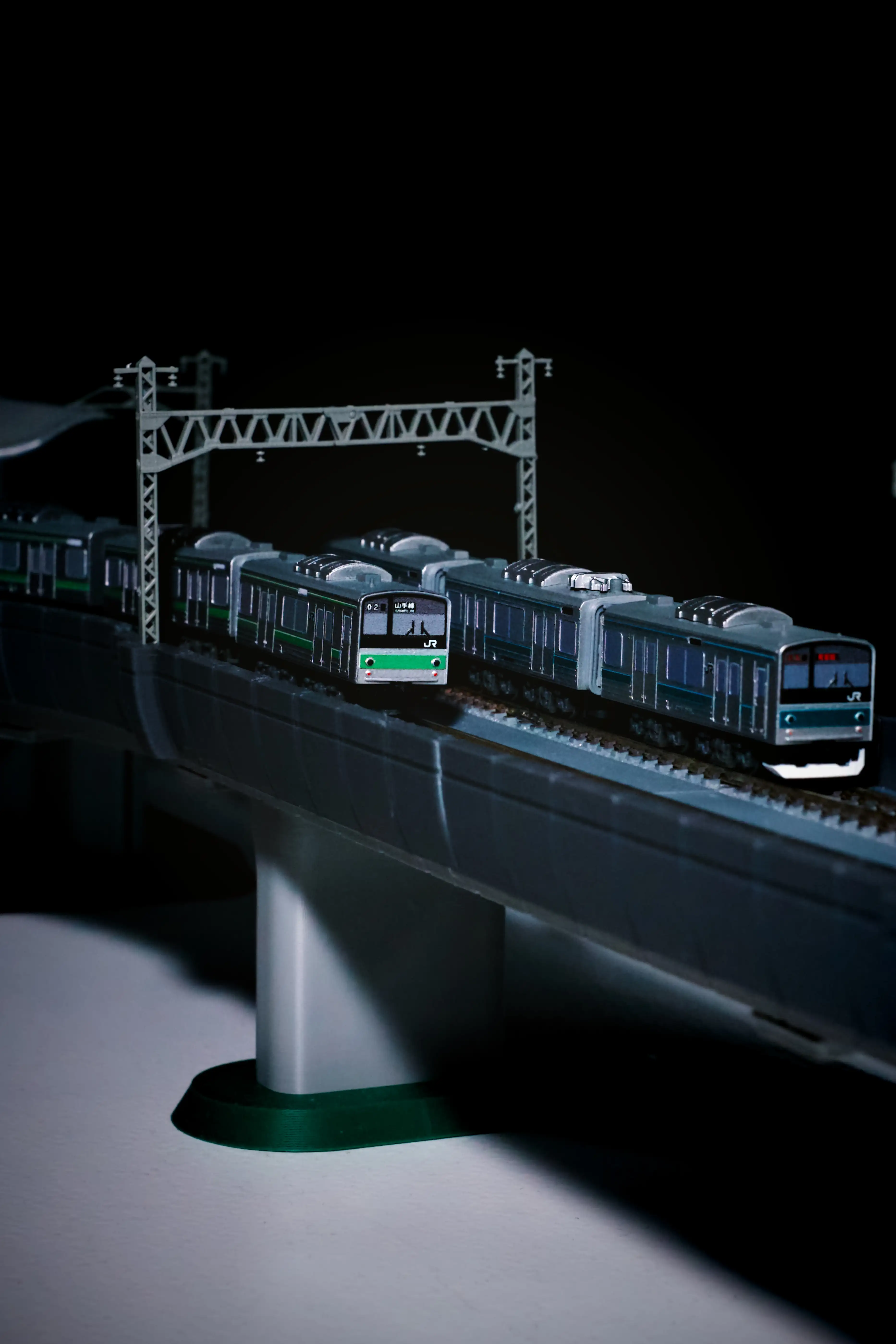
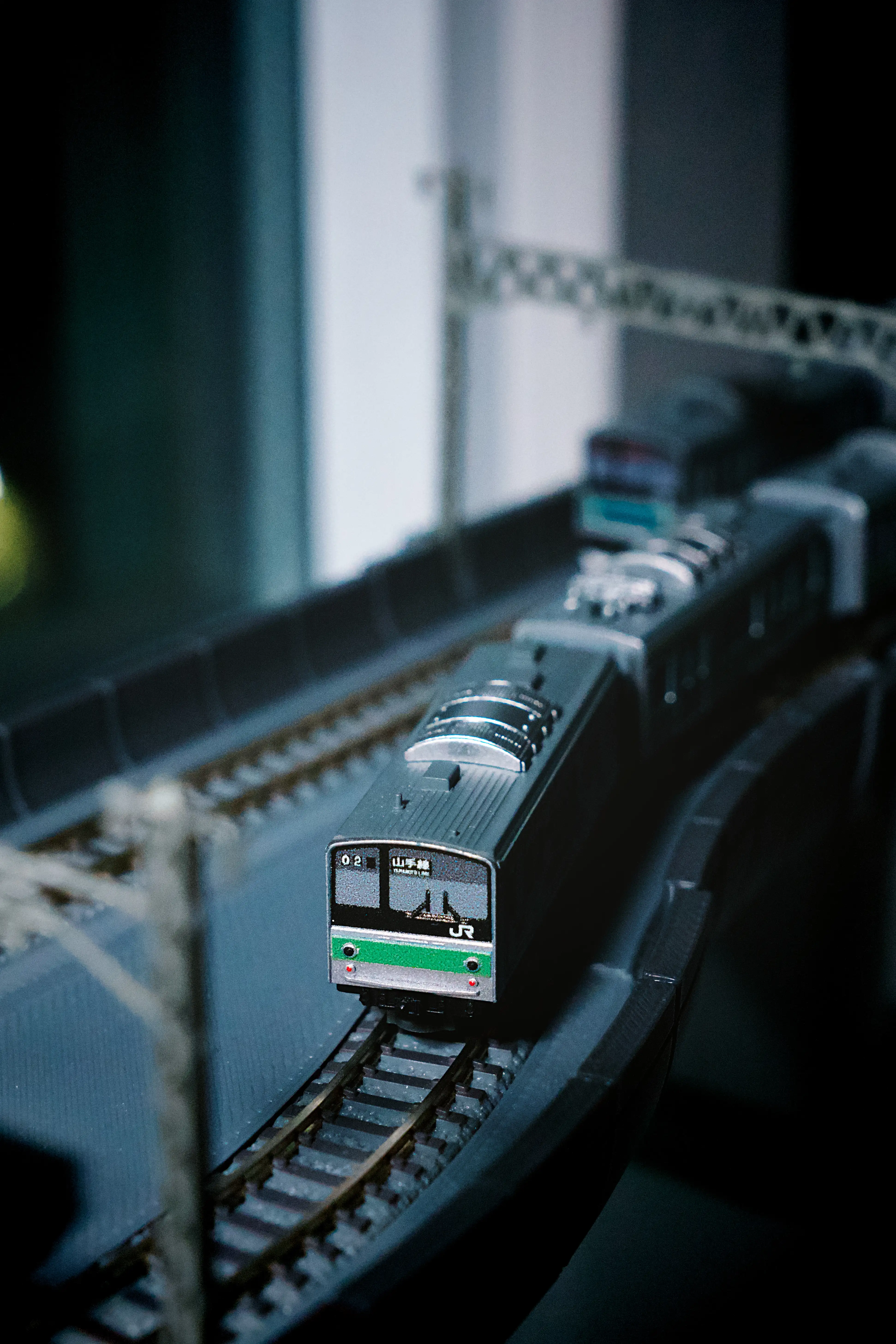
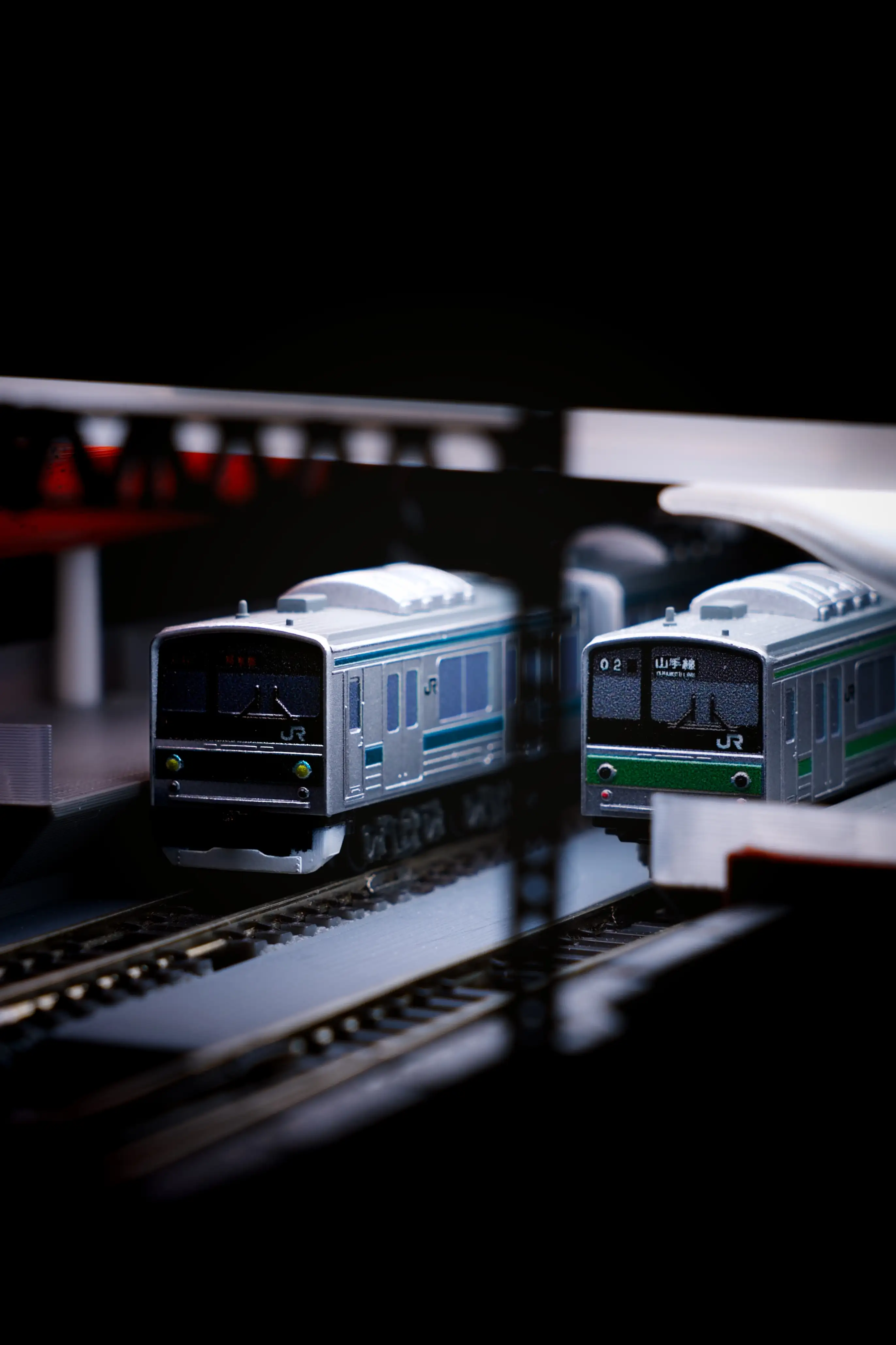
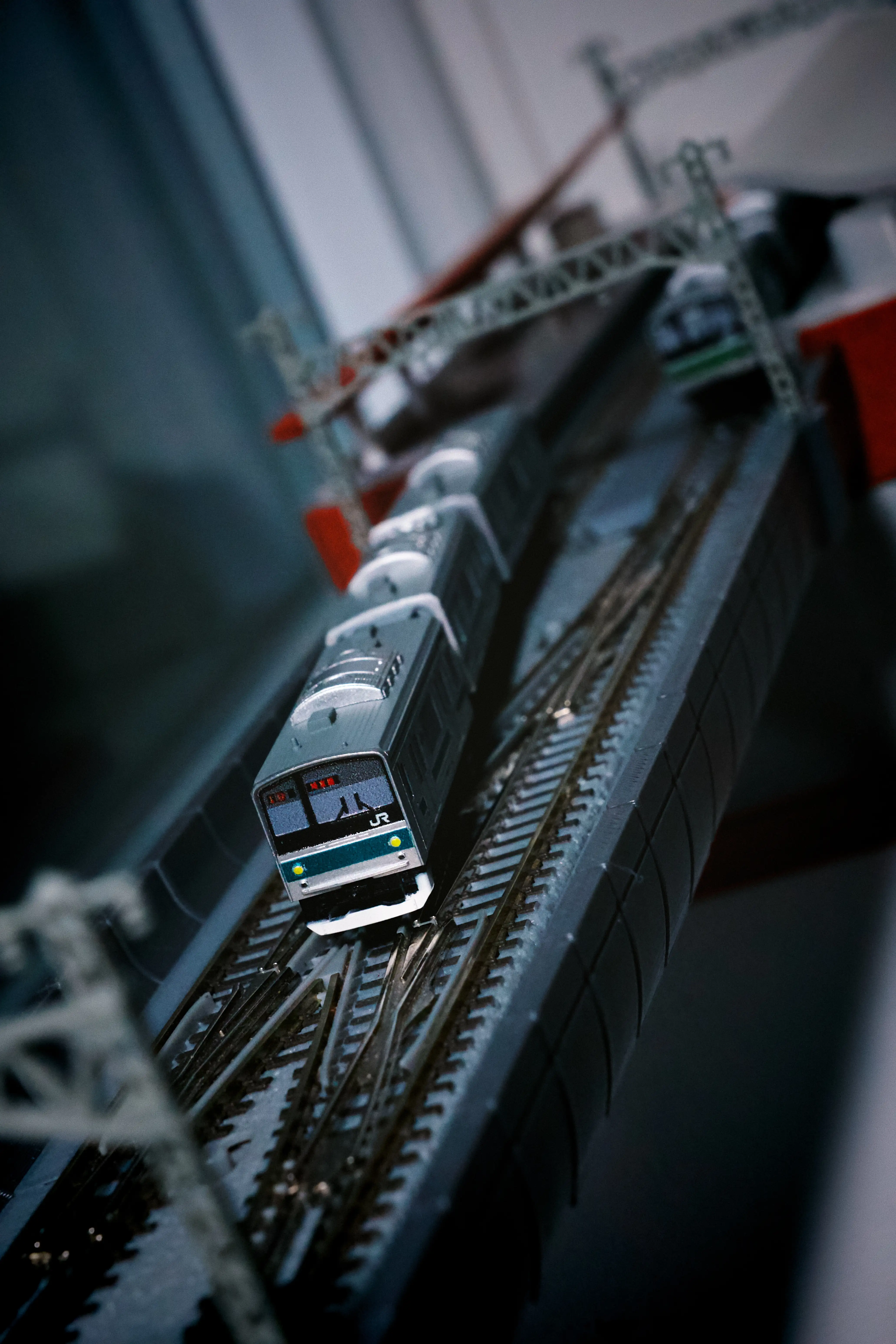
This guide details the specifications and operational setup of my personal z-scale model train layout located on the windowsill at my apartment.
Reddit Posts:
Layout Specifications #
| Name | Downtown Ledge Line |
|---|---|
| Length | 230cm / 7.5ft |
| Depth | 12cm / 4.75in |
| Height | 11cm / 4.33in |
| Power Input | 12V DC to motor shield |
| Data Input | USB Serial to Arduino |
| Number of Blocks | Total: 19 20 when the crossover is in close position, allowing two trains at the same time |
Rolling Stock #
Rokuhan Shorty trains modified for DCC decoding and better power pickup
Materials #
For a two-train operation:
| Item | Count | Link | Notes |
|---|---|---|---|
| Rokuhan Shorty train shell | 2 | one per train | |
| Rokuhan SA003 Shorty trailer | 2 | one per train | |
| Rokuhan SA001 Shorty powered chassis | 4 | two per train | |
| Rokuhan A053 DCC train decoder | 2 | one per train | |
| Rokuhan A034 traction tires | 4 | two per train. pack includes 10 pieces | |
| Weights | numerous | search keyword: “car weights” / “tungsten buffer”. diameter: 0.95cm/0.37in height: various |
|
| MCR gangway cover | 8 | Cults3D | two per gangway gap |
Modification for DCC #
Shorty trains have limited internal space. Although it is possible to fit a decoder inside the motorized car, the decoder sometimes prevents the shell from closing. At the same time, since a reliable pickup is essential for a smooth run under DCC, a design with more pickup wheels is preferable.
Therefore, the front car is repurposed to house the DCC decoder. Instead of a regular trailer car, a motorized car is used because its bogies are already wired. The motor is taken out to free up space. The DCC output cables then run from this front power-collection car to the middle motorized car. Cables running between cars are slightly longer than a straight line, and are intentionally designed to bend at rest. If the cables are too short or rigid, the train may encounter issues navigating curves and S-curves.
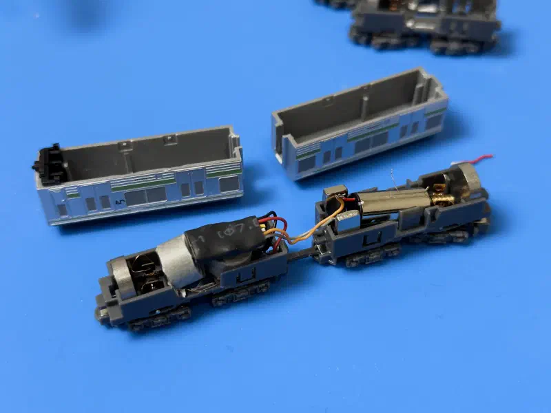
Left: motorized chassis repurposed for power pickup and housing DCC decoder only. The motor is taken out. Rubber tires are removed.
Right: “passive” powered unit, with no power pickup connected. Power is fed from the left car over cables. All four wheels of geared axles have rubber tires.
Gangway ends of the shell are also cut to create space for wires to go through.
Furthermore, to enhance grip and stability, all the geared wheels in the middle motorized car are fitted with rubber tires (only one out of four axles is fitted with tires by default).
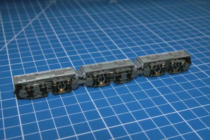
[ P P ] [ P P ][ X X ] [ O O ][ X X ] [ X X ]P: wheels connected for power pickup
O: wheels with rubber tires
Improving pickup using weights #
To improve power pickup, small weights are added inside each car. Certain parts of the chassis and the interior of the train shell are removed to free up space. The weight pieces are wrapped in tape to prevent contact with exposed wires.
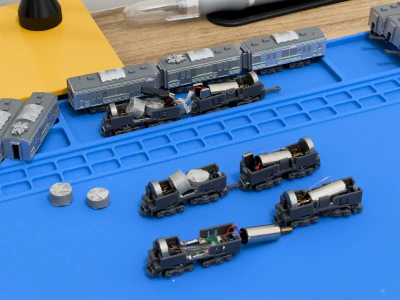
Placement of weights in pickup (left) and motor (middle) cars
Do not use tungsten putty or any semi-solid material. Over time, gravity causes putty to sag and flow. It will seep into bogie gaps or onto electronic components.
Covering gangway gaps #
There is a noticeable gap between coupled shorty train cars, making them less visually realistic, particularly compared to modern transit systems designed with walkthrough gangways. Furthermore, exposed cables running between cars are simply not pleasant to look at. To address this, I designed and printed custom pieces to cover these physical gaps. The pieces are designed with flexible “flaps” to allow movement as the train goes around curves.
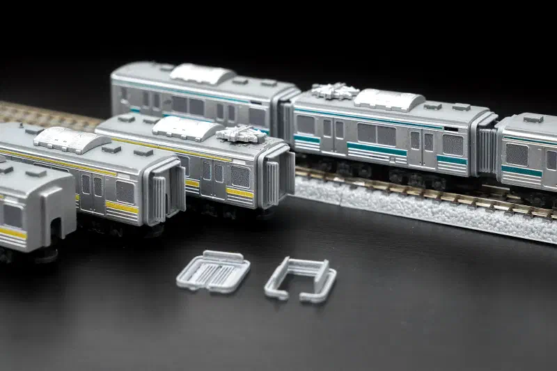
Gangway covers downloadable on Cults3D
Alternative solutions #
Before undertaking the work of modifying your entire fleet into two-car pairs, you can consider:
- Try a standalone DCC-modified cab first, and see how well it performs
- Cleaning the tracks super well at the beginning of every session
- Finding and adding even denser weights to improve power contact
- Chaining two individual DCC-modified cabs together and configuring them with the same address. Now you have a fleet of EMUs!
- I tried that idea, but when one cab is not moving, its locked gears make it even harder for the other cab to push or pull.
- Super advanced: EMU, but both decoders drive both motors?
Tracks & Supporting Structure #
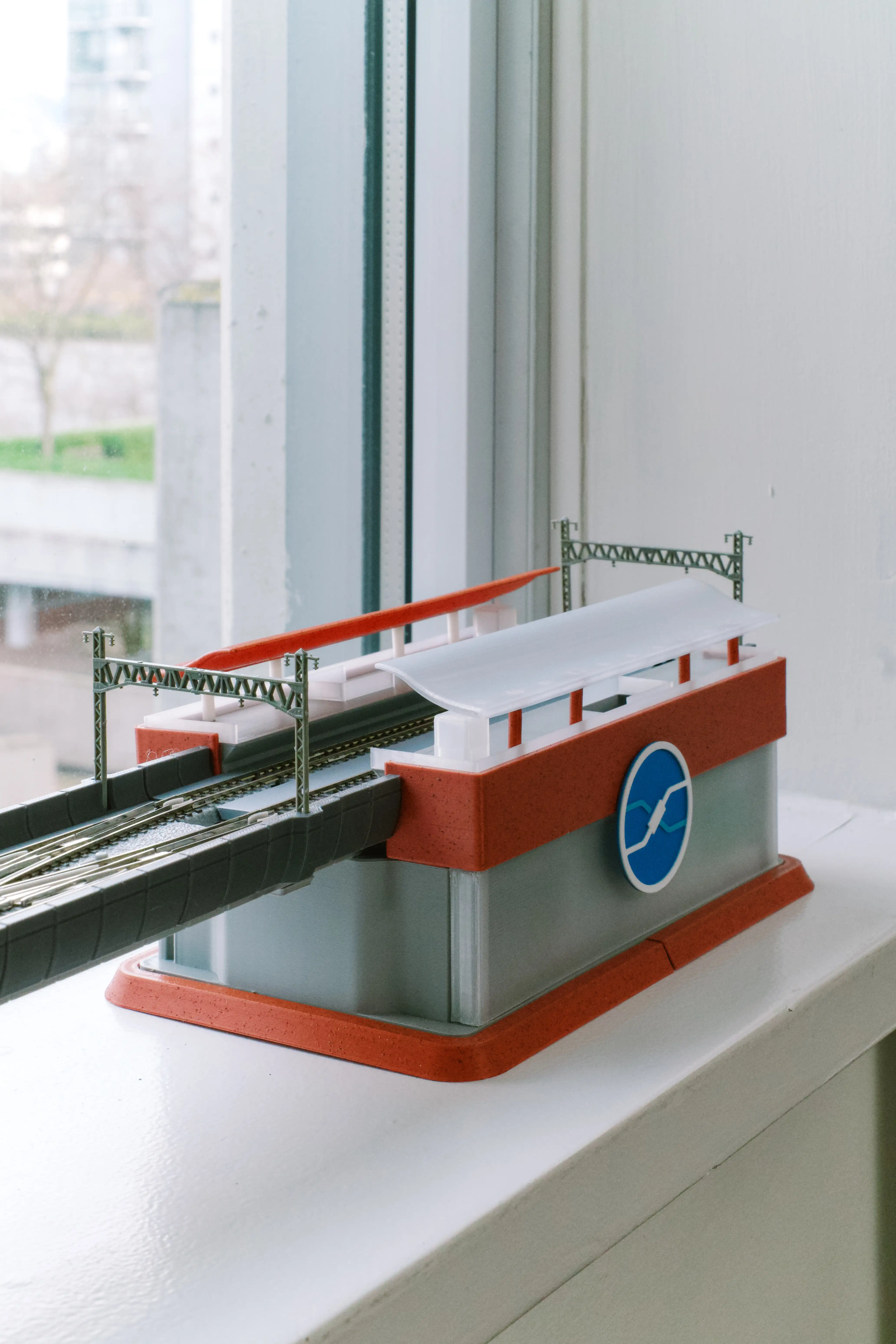
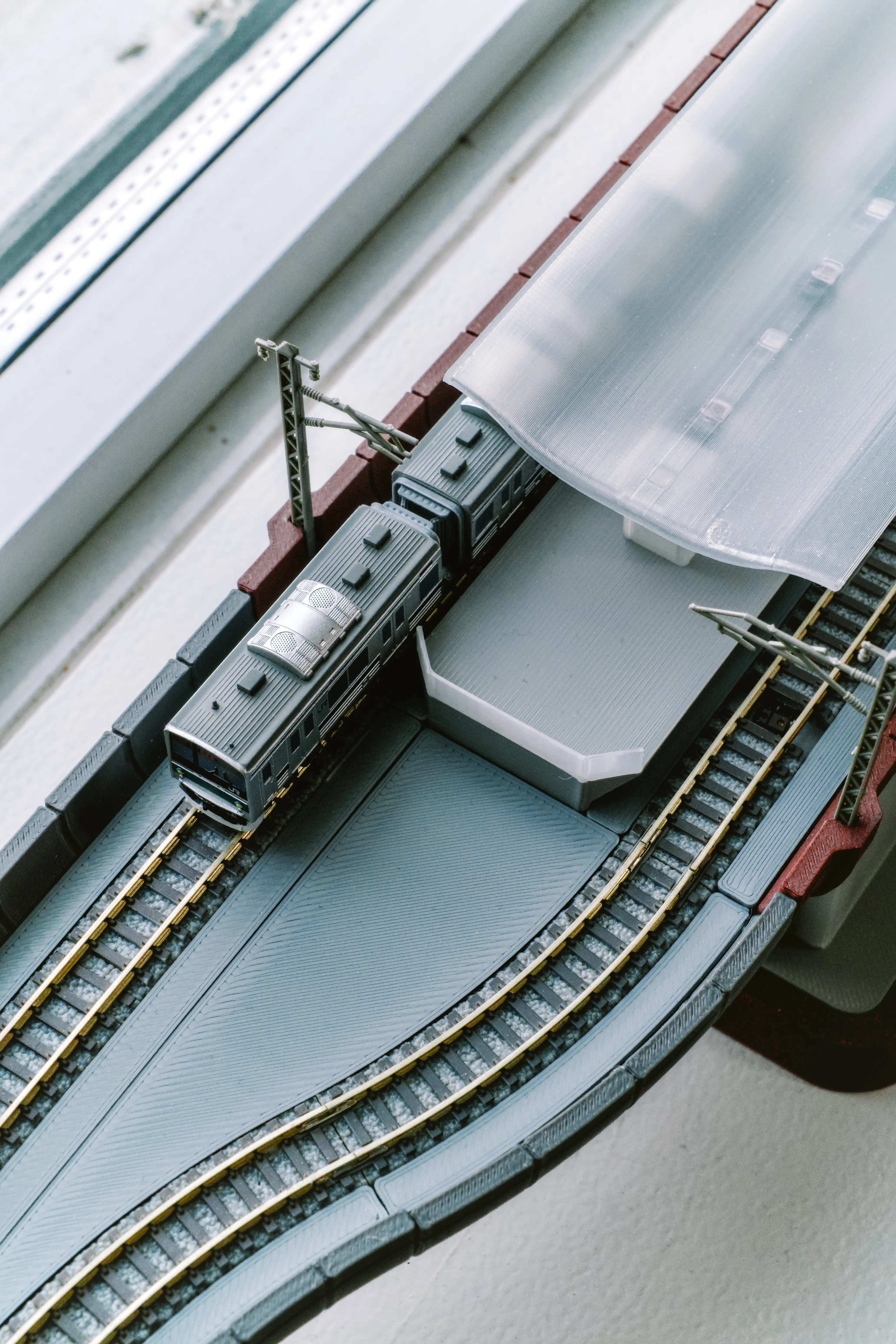
Custom 3D-printed designs for supporting elevated tracks
Materials #
For a three-station layout:
| Item | Count | Link | Notes |
|---|---|---|---|
| Rokuhan tracks | numerous | R001 110mm straight R024 55mm straight R019 R127mm curve R029 end bumper |
|
| Rokuhan R023 remote turnout | 1 | “non-power routing” mode: power goes to all tracks | |
| Rokuhan R078 double crossover | 1 | “non-power routing” mode: power goes to all tracks | |
| Rokuhan S020 overhead mast (single) | 6 | pack comes in 10 pcs | |
| Rokuhan S021 overhead mast (double) | 9 | pack comes in 10 pcs | |
| MCR guideway segments | numerous | Cults3D | guideway segments, segment connectors, sensor holders |
| MCR side walls - style 2 | numerous | Cults3D | |
| MCR support columns - styles 2 and 3 | numerous | Cults3D | at H40mm. hiding sensors |
| MCR segment with utility storage | 2 | Cults3D | one per turnout |
| MCR station - side - 165mm | 2 | Platform: Cults3D Station: Cults3D |
at H40mm |
| MCR station - island - 220mm | 1 | Platform: Cults3D Station: Cults3D |
at H40mm |
| MCR station accessories | numerous | Cults3D |
The entire guideway structure is designed and 3D printed to support elevated tracks. It provides several benefits:
- Reduce footprint of surface use, just like in cities.
- Eliminate the need of tools and materials to drill holes in boards.
- Modular design to keep the layout flexible for expansion and relocation, particularly suitable for rented spaces.
- Provide concealed conduits for cables to run along tracks.
- Provide space and housing for electronics such as DCC accessory decoders and sensor boards.
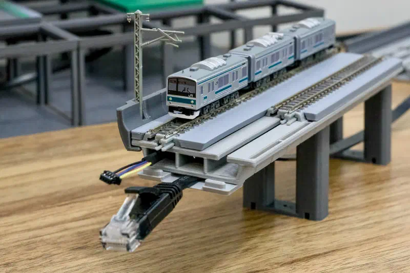
Guideway system with space for cables to run through or under.
Please check out the full collection of this modular system.
Color Guide #
Choose muted colors for the main guideway structure and use accent colors to highlight each station.
These are the materials I use:
| Part | Material | Brand |
|---|---|---|
| Guideway structure, pillars | PLA basic gray | Bambu Lab 10103 |
| Track holders | PLA matte ash gray | Bambu Lab 11102 |
| Side walls | PLA basic dark gray | Bambu Lab 10105 |
| Pillar foundation (foot) | PLA basic mistletoe green | Bambu Lab 10502 |
| Platform top surface | PLA matte ivory white | Bambu Lab 11100 |
| Glass and any translucent parts | PLA translucent | Elegoo |
| Escalators and any metal parts | PLA basic silver | Bambu Lab 10102 |
| Station accent color 1 | PLA wood classic birch | Bambu Lab 13505 |
| Station accent color 2 | PLA wood rosewood | Bambu Lab 13204 |
| Station accent color 3 | PLA marble red granite | Bambu Lab 13201 |
3D Printing Process #
In addition to common FDM 3D printing practices, there are a few things to note:
- Material shrinkage: guideway pieces must match the length of track pieces. Print a L110mm straight guideway piece in targeted material and configurations, measure the actual size, compare it with an actual 110mm track piece, then apply scaling in slicer software.
- My printer (unenclosed Bambu Lab A1 mini) and material (PLA) setup requires a 100.5% scaling for all pieces.
- Material characteristics: choose print material depending on where the layout will be placed. A material that is resilient under UV exposure might be required if it is regularly under sunlight.
- Although my layout is on the windowsill, it is never exposed to direct sunlight, since I live at a relatively high latitude and the windows face north.
Electronics & Wiring #
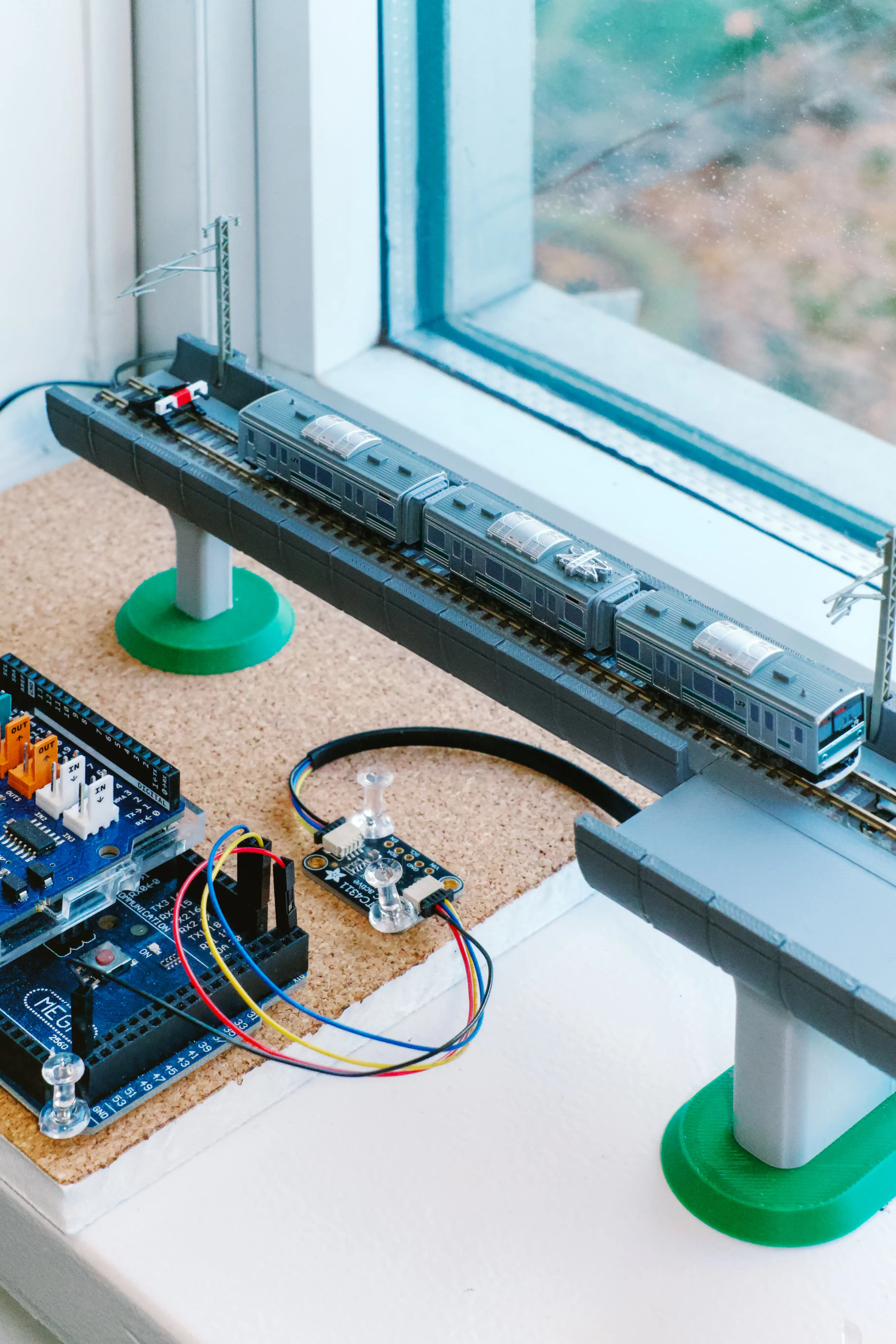
DCC powering, turnout controls, and sensor inputs aggregated and concealed to minimize visible cables.
Materials #
| Item | Count | Link | Notes |
|---|---|---|---|
| Arduino Mega with motor driver | 1 | DCC-EX | or any model that supports DCC-EX |
| ISE TrainSpotter with Remote Sensor | 19 | Iowa Scaled Engineering |
use more for finer blocks |
| Adafruit MCP23017 I2C GPIO Expander Breakout | 3 | Adafruit | one per station |
| Adafruit LTC4311 I2C Extender / Active Terminator | 1 | Adafruit | |
| Rokuhan A008 narrow feeder cable | 3 | one for power supply and one per turnout/crossover | |
| Rokuhan A060 DCC accessory decoder | 2 | one per turnout | |
| Small breadboard | 3 | one per station |
Wiring Diagram #
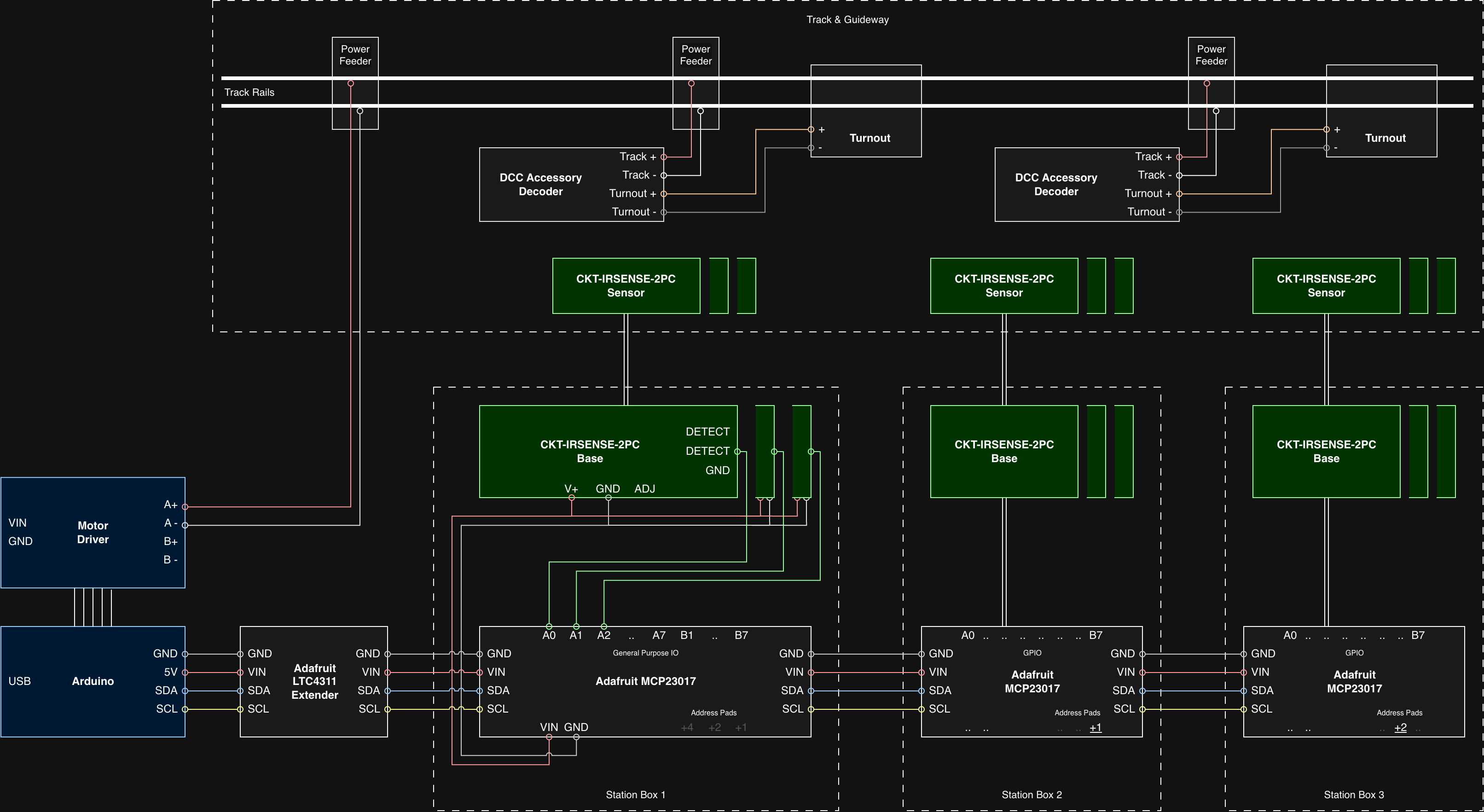
System Areas & Components #
Central Control #
DCC-EX Command Station on Arduino: Main unit to manage core control logic, process I2C bus inputs from the sensors/expanders, and emit the digital DCC signals required for train operation and motor driver power delivery.
Adafruit LTC4311 I2C Extender / Active Terminator: Provides active termination on the I2C lines to maintain signal integrity over physical distance.
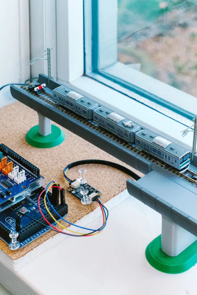
Only two cables running into guideway structure: DCC power and I2C signalling
Under-Track & Guideway Segment Installations #
Track Rails & Feeders: Physical running lines powered by feeder wires dropping down from the rails.
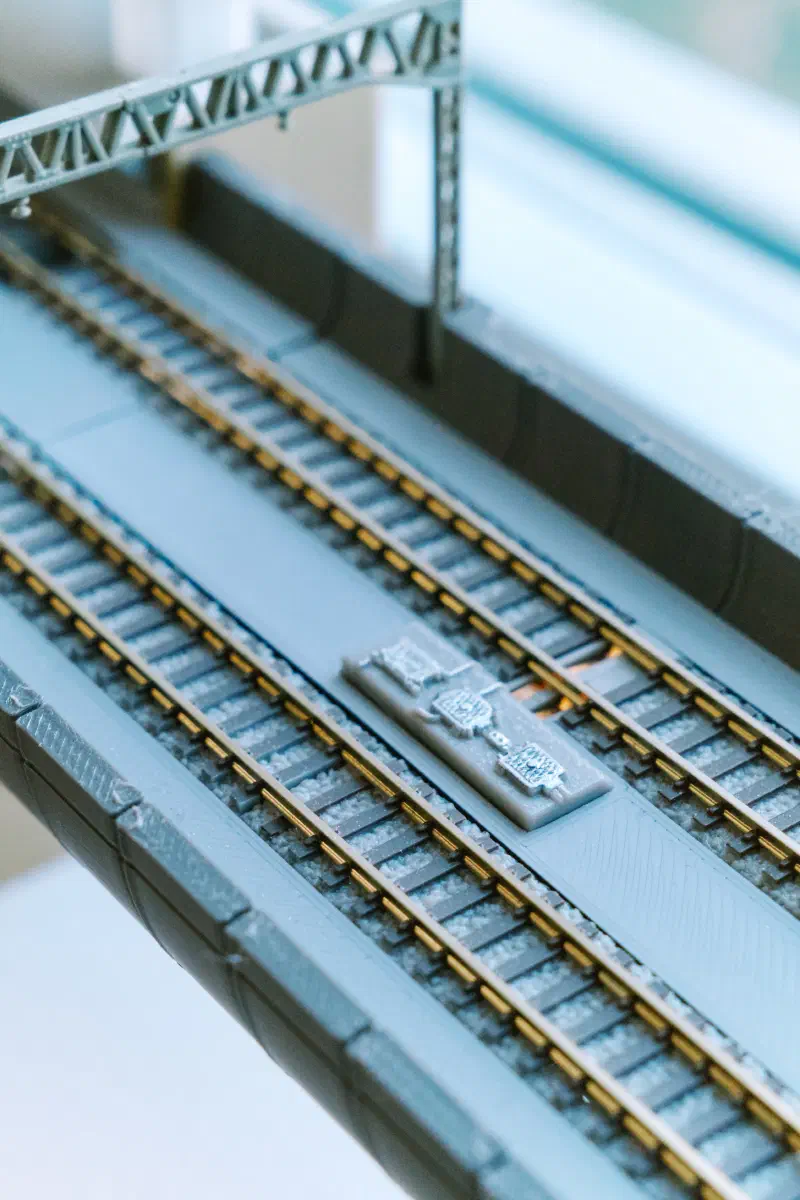
Power feeder for getting DCC power to and from track rails
Turnouts & DCC Accessory Decoders: Track switches driven by decoders.
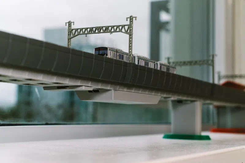
Decoder and additional cables hidden inside segments with utility storage
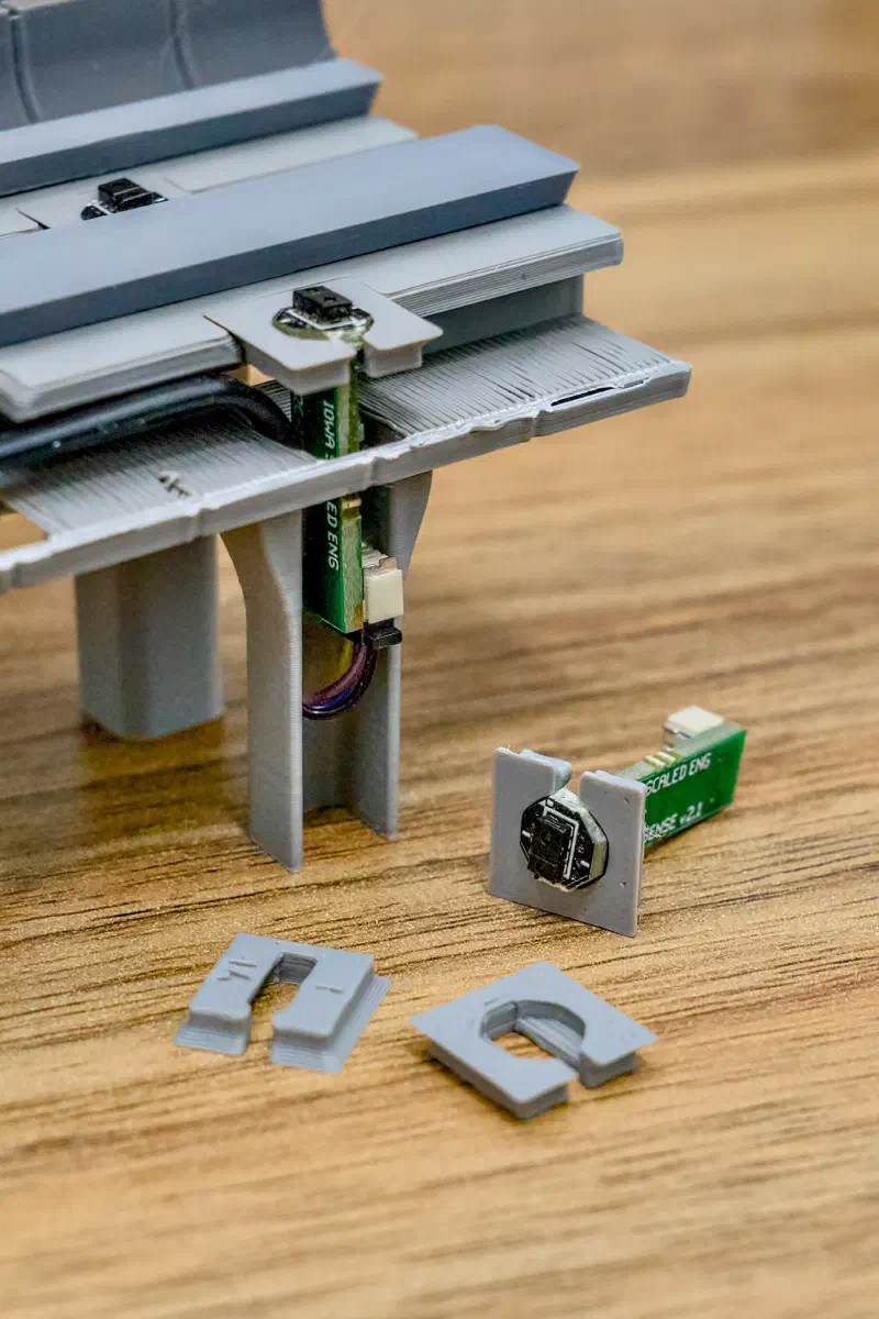
ISE TrainSpotter Sensors: Optical sensor heads positioned along the guideway to detect train presence. Hidden under tracks and inside support columns. Cables run under tracks to the nearest station box for signal conversion and aggregation.
Station Boxes #
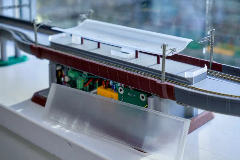
ISE TrainSpotter Base Boards: Interface with sensors and supply logic state outputs to the expander pins.
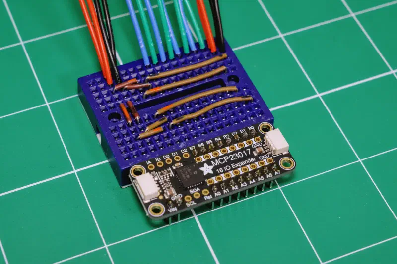
Adafruit MCP23017 GPIO Expanders: Receive and aggregate multiple sensor inputs to I2C stream, and provide I2C daisy-chaining for the next station box. Each expander has a unique address by soldering different pad combinations.
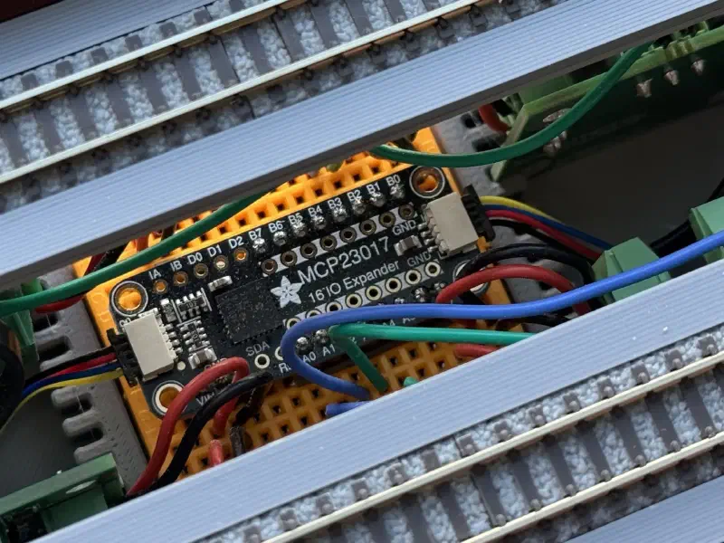
From left to right:
- Incoming I2C cable from Arduino
- VIN and GND to sensor boards
- Signal outputs from sensor boards
- (Back side of the expander) address pads soldered individually
- Outgoing I2C cable to the next station
Alternative Designs #
- Dedicated DCC power bus under track: In the current setup, turnouts receive their control signal and power directly from local track feeders. This keeps the setups local. Alternatively, a dedicated power/DCC bus line running under the guideway can supply all decoders directly. While this adds initial installation work and wiring under the benchwork, it provides cleaner power distribution and isolates track voltage drops from accessory operation.
Expanding the System #
When adding new stations to the layout, follow these steps:
- Connect to the main wiring: Daisy-chain the 4-wire power and I2C bus into the new station box.
- Set a unique I2C address: Bridge the onboard address pads (combinations of
+1,+2, or+4) on the new MCP23017 board to assign a unique hardware address (up to 8 total expanders on a single bus). - Relocate I2C termination: Move the LTC4311 active bus extender so it sits at the physical end of the expanded I2C bus (after the final station box) for optimal line capacitance handling.
Controlling System #
A custom software interacts with DCC-EX command station for train control, signal processing, and passenger displays.
Main software #
A server program managing trains and tracks
Start time inputs:
- track schematics
- track types and speed limits
- turnout locations and addresses
- sensor locations and addresses
- station locations
- train initial locations addresses
- service line definition
- station sequence and platform preference
- use specific platforms at left and middle stations
- at the right station, pick either platform depending on availability
- additional waypoints / stops
- turnaround track beyond the left station
- station sequence and platform preference
Runtime inputs:
- presence of trains above sensors
- commands from control panel
Runtime outputs:
- DCC-EX native commands to Command Station via USB Serial
- track power on/off
- train movements
- turnout positions
- train and track status published for control panel and passenger displays
Core train operation logic:
- remembers (not detects) a train’s current location
- decide the train’s next desired location
- when multiple locations are acceptable (e.g. platforms at terminal stations), pick the one that is available
- calculate movement path
- reserve blocks the train’s upcoming movements
- when blocks are granted:
- change turnout position if any
- issues train movement command
- expects a sensor to be triggered by the train
- once the sensor is triggered and resets, remembers the train’s new location
- releases block reservations for the train behind
- repeat
Control Panel #
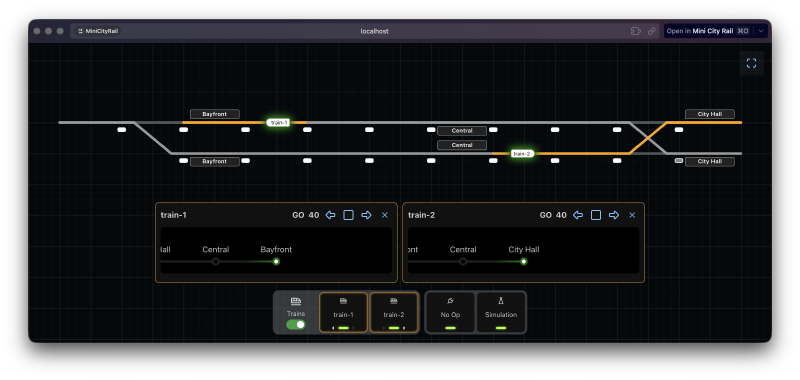
A web interface displaying train and track status and taking user commands to main software
Passenger Display #
A lightweight app rendering train status as images displayed on small LCD screens